Bike Theft Prevention System
A proof-of-concept embedded system designed to deter bike theft, authenticate owners with biometrics, and provide location tracking after a theft event.
Introduction
Our goal was to create a system for securing a bike that took less time to use than a traditional U or cable lock. Bike theft is a serious problem on Middlebury campus, with it happening to people we know often. This is a problem at Universities across America as well.¹ At the same time, traditional locks are a hassle to use when moving around campus as much as the average student, and many students tend to not lock their bikes, exacerbating the issue.¹ Our goal was to make a bike theft deterent system that would require little work to operate and strongly discourage bike theft.
In order to lock and unlock the bike, we determined that a fingerprint sensor would be ideal for a quick and easy lock and unlock process. We use an accelerometer and GPS combination to detect when the bike is being stolen. Once the system determines a theft attempt is underway, it begins blaring a loud horn (135db+) and tracks the bike’s location via an onboard GPS. The GPS data is sent to an MQTT Server (Adafruit IO Dashboard, in our case) for the bike owner to device on their personal devices. An OLED display is used to display the lock status, battery, gps information, and handle the finger enrollment process (adding new authorized fingerprints).
Originally, we were interested in a physical lock mechanism as well, but we realized that it would be much easier and just as effective to use a horn. What is especially nice about this approach is that a bike may be secured regardless of where it is, without having to rely on a bike rack.
We also decided that this project would perfectly fit the course objectives and motivations for learning embedded systems. We expanded our knowledge of integration of many different peripherals, using UART, SPI, and I2C protocols. We learned new ways of handling parallel code with FreeRTOS, and how to deal with the constraints of processing power. We were able to identify a real world issue and devlop a solution prototype (as gimmicky as it is in reality). Overall, we were able to apply our skills learned throughout the semester into a device that is properly interactable and functional in the real world.
Methods
MCU
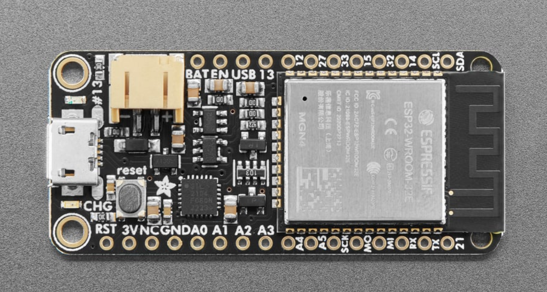
We used the Huzzah32 ESP32 Feather by Adafruit due to its powerful dual core CPU, WiFi, and deep sleep capabilities. We also already had on hand, and didn’t have any need to use a different board. We used PlatformIO to build the structure of our project. We use I2C, SPI, and UART protocols to communicate with our acceleromter, OLED, fingerprint sensor, and GPS module. The ESP32 handles all the tasks for these peripherals. The ESP32 also handles a MOSFET connected to a horn wired to a 12V power source. This allows the ESP32 to “power” the horn with 12V and many amps, while remaining safe and secure on its 5V line. We also make effective use of the ESP32’s dual core. Our sensor loops are handled as FreeRTOS tasks which allow us to spread out CPU load and ensure our code is non-blocking.
Peripherals
Fingerprint Sensor
We are using Adafruit’s “Rugged Panel Mount Fingerprint Sensor with Bi-Color LED Ring - R503” as our fingerprint sensor. This is the main entry into the BTDS, as it is used to arm and disarm the alarm system. The sensor exchanges data with the MCU on the RX (16) and TX (17) pins, as well as a separate interrupt pin (27) for wakeup. With onboard memory, the sensor manages all fingerprint reading, verification, and storage internally.² The red, pink, and blue LED ring is configured to show when the system is woken via the sensor. It also indicates if a scan is read as a match, and, with the OLED, walks the user through enrolling a new fingerprint.
We are using Adafruit Fingerprint Sensor Library ("fingerprint.h") to communicate with the fingerprint sensor. It’s relatively straightforward:
Adafruit_Fingerprint finger = Adafruit_Fingerprint(&Serial1); // Serial 1 uses the default HardwareSerial at UART 1

void setup() {
 finger.begin(57600);
}
Then you can access all sorts of functions such as finger.LEDcontrol(), finger.getImage(), finger.search() etc. to setup checking fingerprints.
More info can be found on the Adafruit Fingerprint Sensor Overview

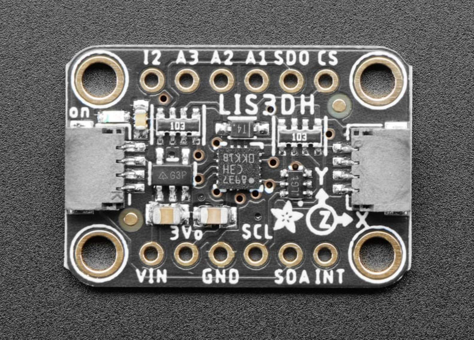
Accelerometer
We are using Adafruit’s LIS3DH acceleromter. It features high sensitiviy, 3-axis detection, and low-power modes. It is configured to supply an interrupt signal when a certain threshold of motion is met.³ Our acceleromter is primarly used to wake up our system. When the accelerometer surpases its motion detection threshold, it will trigger the ESP32 wakeup process. Once the interrupt is triggered, the accelerometer moves into a higher-power mode, where it reads for acceleration more frequently. New acceleration events will be stored. Before the ESP32 goes back to sleep, it will check if there has been a recent acceleration (last ~5 seconds). If there has been, then we can assume that the bike has been in motion for at least 25 seconds, and this will trigger the alarm.
While Adafruit makes a library for this sensor, it does not contain the interrupt configurability that we needed. So, we ended up having to create use writeRegister and readRegister to perform the accelerometer configuration via its datasheet
We’re not actually ever reading from the accelerometer, rather it’s just sending interrupt signals whenever it detects enough movement. So our accelerometer code is just configuring an interrupt threshold, range, duration, etc. We also have a function that will clear the acceleromter interrupt, allowing more to be sent.
More info can be found on the Adafruit LIS3DH Overview
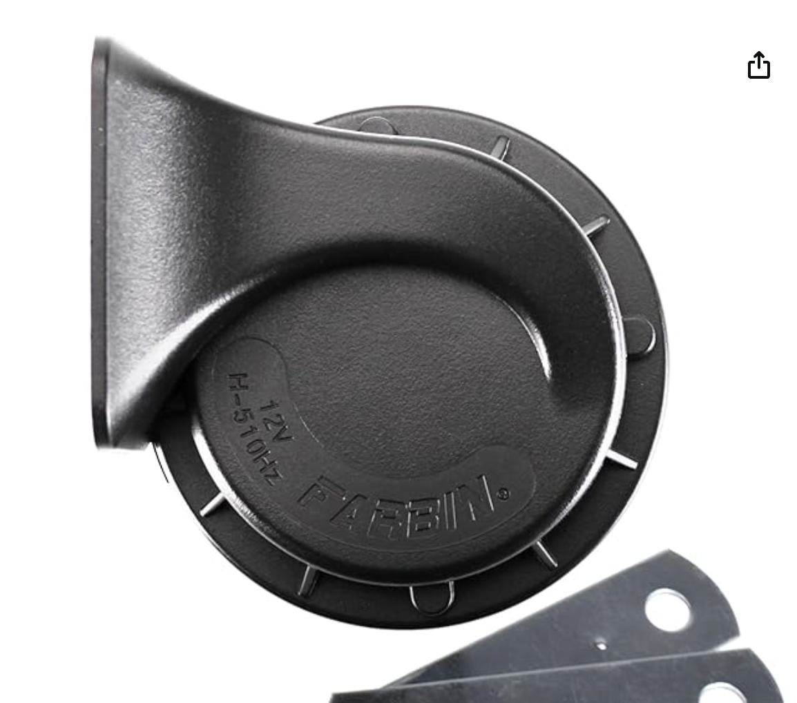
Horn
The horn is supplied with a 12v power supply and requires many more amps than is supported by the ESP32 and peripherals. For this reason, we purchased a 12V battery, voltage regulator, and MOSFET. The voltage is regulated down to a safe 5V for the ESP32, and the ESP32 controls the horn indirectly via the MOSFET. The MOSFET allows the MCU to allow or disallow current to the horn directly from the battery without directly supplying the current at the level the horn expects.
GPS
The GPS is connected via its TX (21) pin to the ESP32, which makes up half of an SPI connection. In the issues section this will be explained. As it stands, the GPS provides data in the National Marine Electronics Association (NMEA) data format. When the ESP32 wakes up, its begins reading from the GPS sensor. This is then parsed using an Adafruit library and stored at the initial wakeup of the ESP32 once at least 6 satellites have been found. Before the ESP32 goes to sleep, it compares the latest GPS reading to the initial reading and calculates the distance between those coordinates. If it detects that the system has been moved more than a threshold distance (in our case 10 meters). If this threshold is exceeded, then the ESP32 moves into the alarm state.
We are using the
HardwareSerial GPS_Serial(GPS_UART);
Adafruit_GPS GPS(&GPS_Serial);
And then parse NMEA data from the serial line:
 while (GPS_Serial.available())
    {
      char c = GPS.read();

      if (GPS.newNMEAreceived()) {
        // can access GPS object here
      }

OLED Display
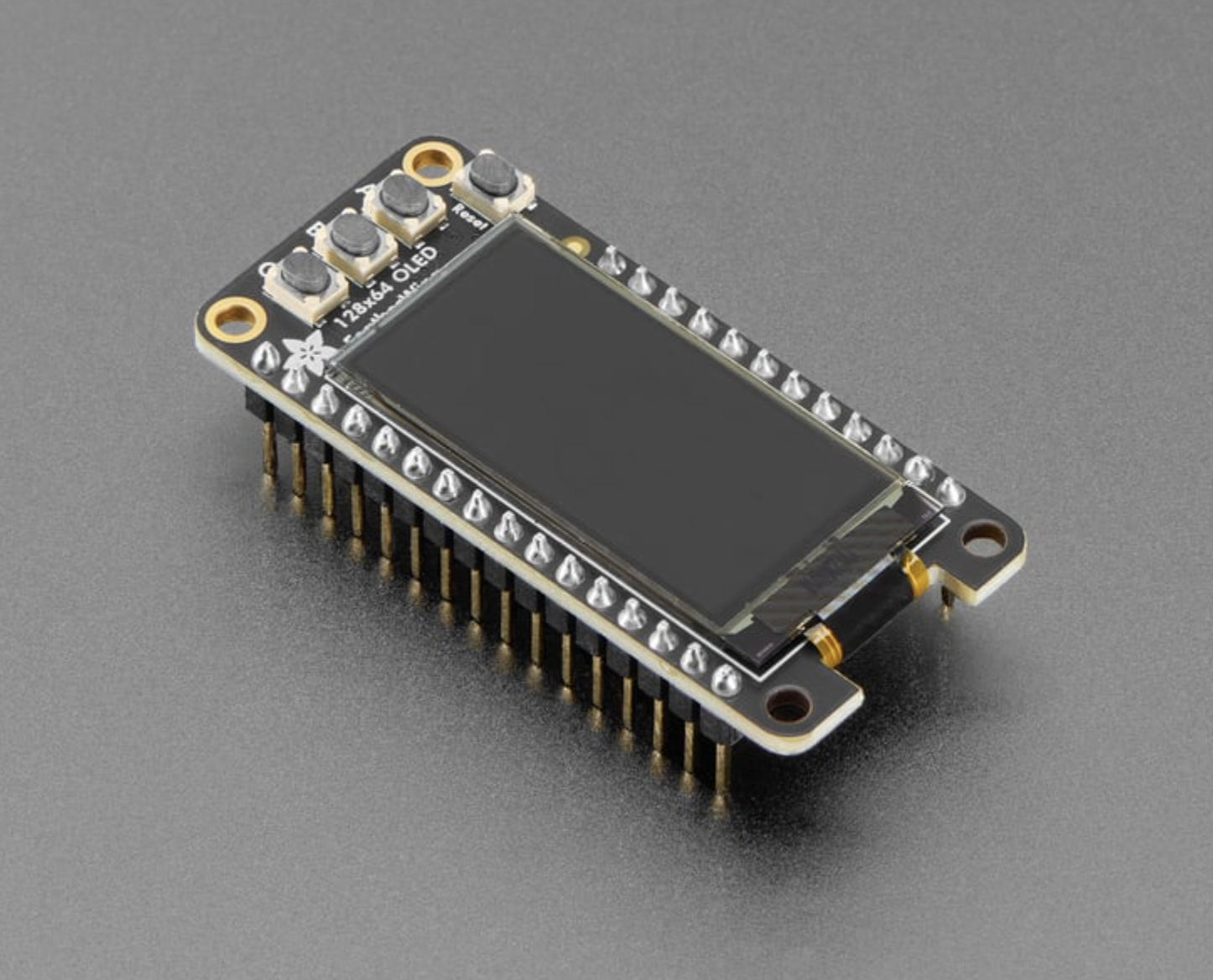
We decided on the Adafruit 128x64 OLED FeatherWing due to its ability to connect to the MCU easily, its simple input system, and modest graphical capabilities, being limited to black and white.
The display is used to give the user information, and its three input buttons are used for the user to communicate to the system. It physically acts as a wing to the MCU, sitting directly on it. It communicates via SPI, and uses the Adafruit SH110X graphics drivers (Adafruit SH110X library). The Adafruit GFX library provides commands to display text, and images.
When the device is in sleep mode, the screen is off. Once awake, when the A button is pressed, the OLED displays lock/unlock status. The B button handles the fingerprint enrollment process, assuming the device is unlocked. The C button displays the GPS status, giving the current connected satellite number, coordinates, and movement from initial position. When the device goes to sleep, the screen will become blank again.
We referenced the code provided by the device supplier to write our code for the display.⁴
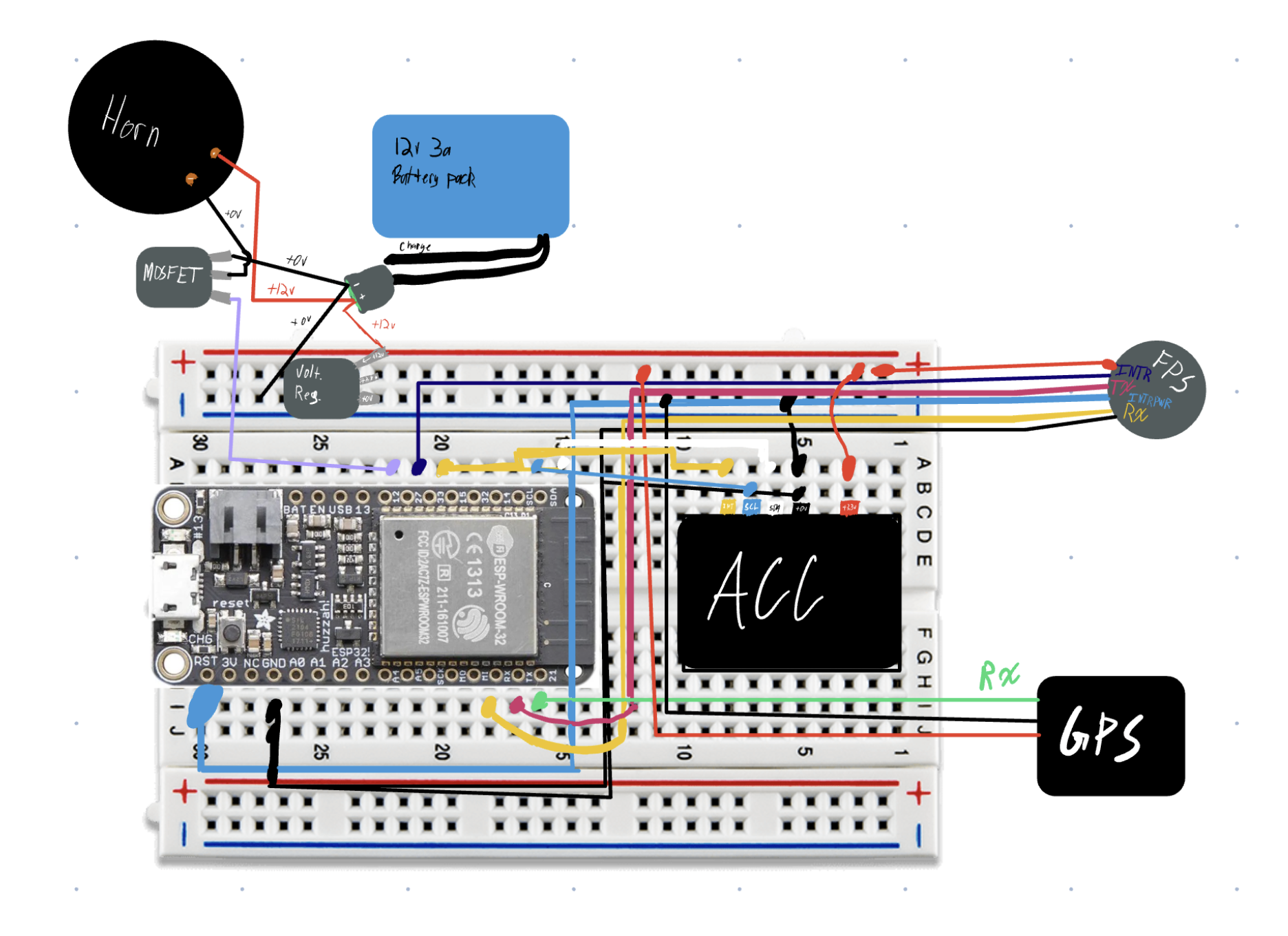
Wiring Diagram
Code Structure Flowchart
Bill of Materials
| Item | Supplier | Cost | Store link |
|---|---|---|---|
| Huzzah32 MCU | Adafruit | 21.95 | https://www.adafruit.com/product/3619 |
| Fingerprint sensor | Adafruit | $39.95 | https://www.adafruit.com/product/4651 |
| Feather OLED | Adafruit | $15.95 | https://www.adafruit.com/product/6313 |
| GPS Module | Adafruit | $29.95 | https://www.adafruit.com/product/4279 |
| Car Horn | Amazon | $12.99 | https://www.amazon.com/dp/B08B4LTRJX |
| Battery Pack | Amazon | $18.56 | https://www.amazon.com/dp/B09DP9D8Q4 |
| Accelerometer | Adafruit | $4.95 | https://www.adafruit.com/product/2809 |
| Regulator | Adafruit | $1.25 | https://www.adafruit.com/product/2165 |
| MOSFET | Adafruit | $2.25 | https://www.adafruit.com/product/355 |
| Total | — | $124.85 |
Results
A video demonstration of the lock in action can be found here: https://drive.google.com/file/d/1twOzUNFAkOQMooSFh1Hvug4dFZvrGIfw/view?usp=share_link
Areas of success: The code and logic flow is all working successfully, and almost all of are peripherals are effectively integrated into the system.
Areas of failure: Currently, we are unable to get the horn to function. While it works when given stand-alone power, it cannot be toggled by the ES. Additionally, we had trouble powering the MCU from the pinouts/breadboard, so we are powering it separately from another battery pack, this one 5v. The form factor is not completely seamlessly integrated into a bike, but could be relatively easily connected via zipties.
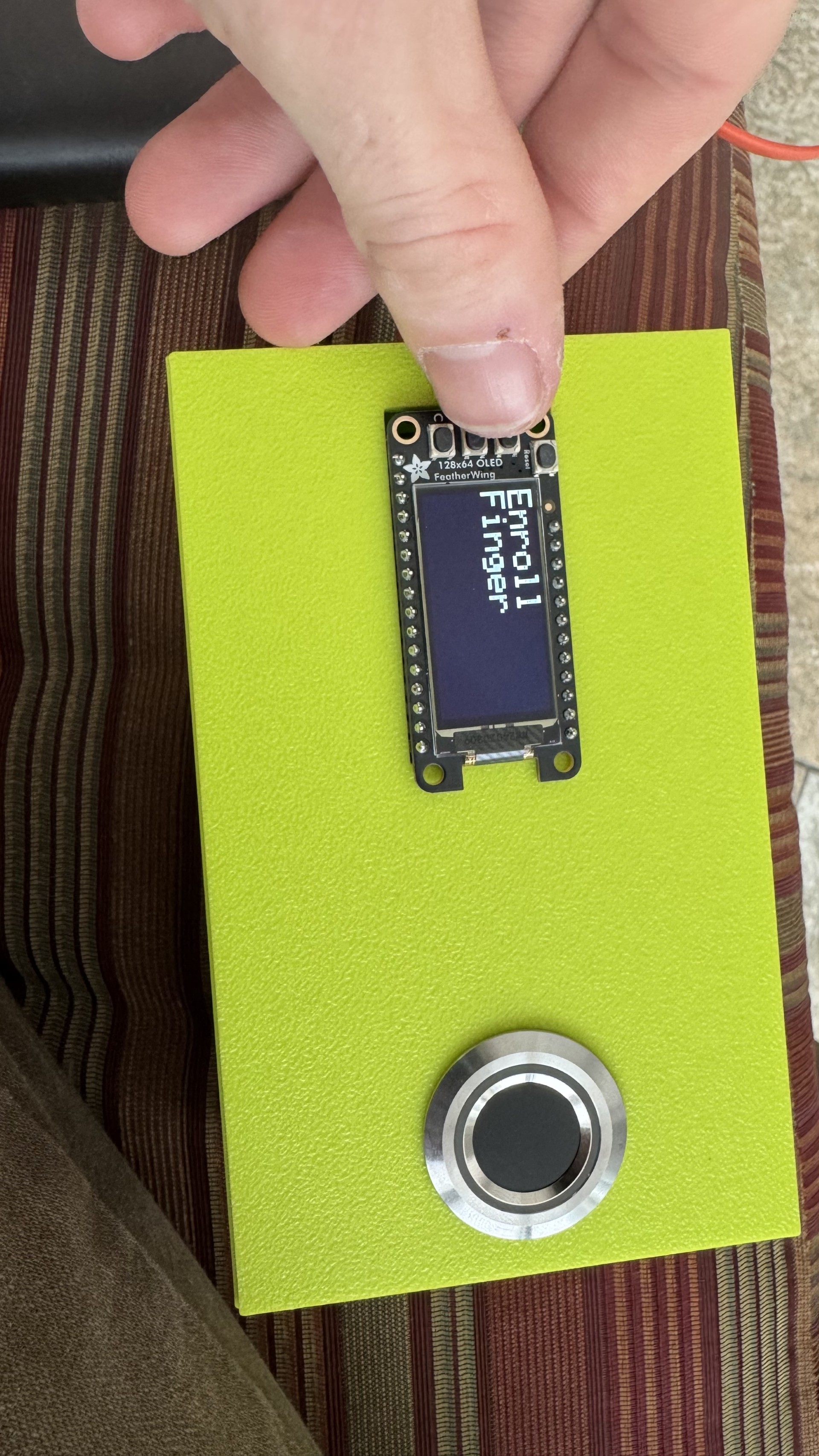
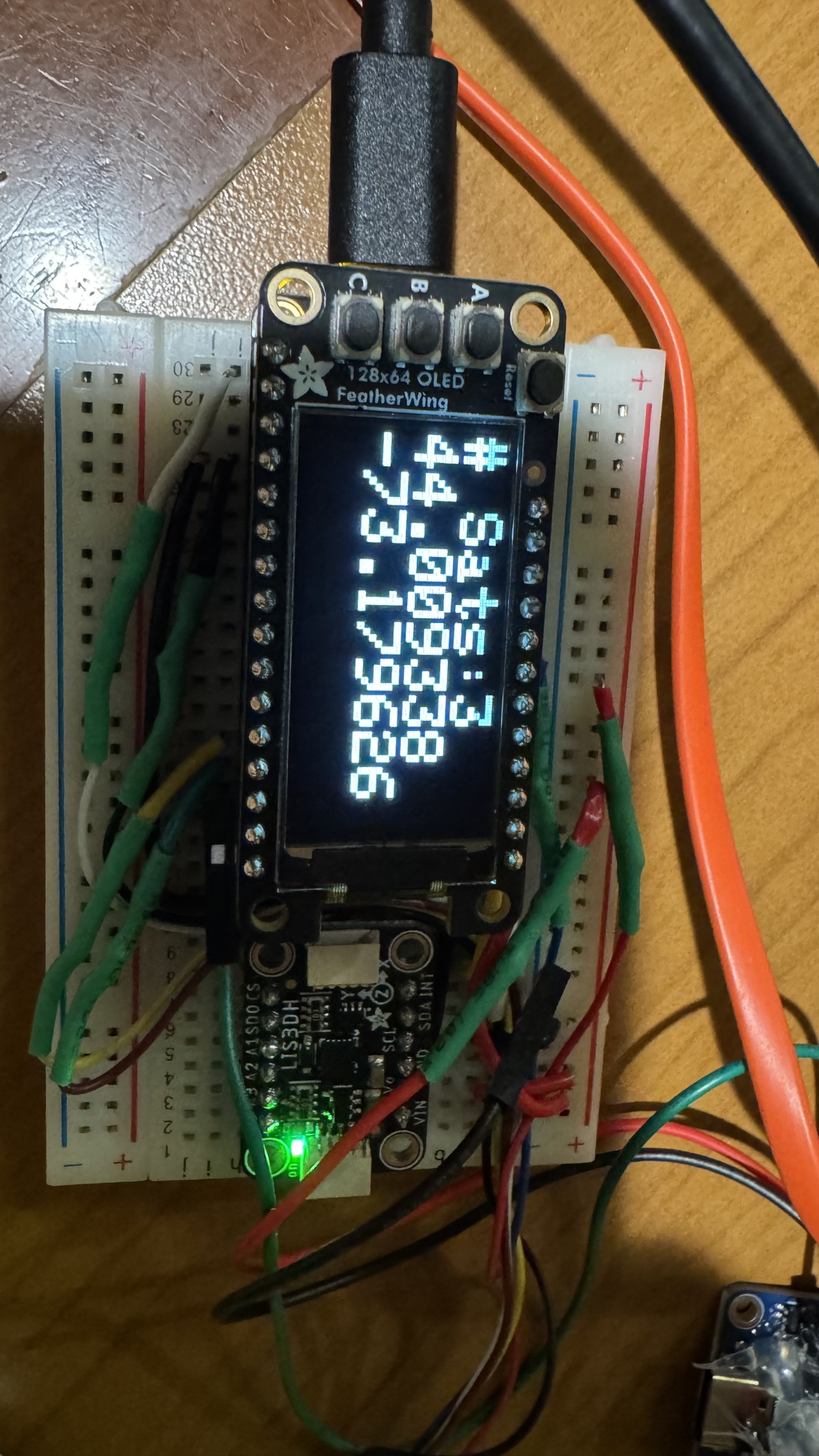
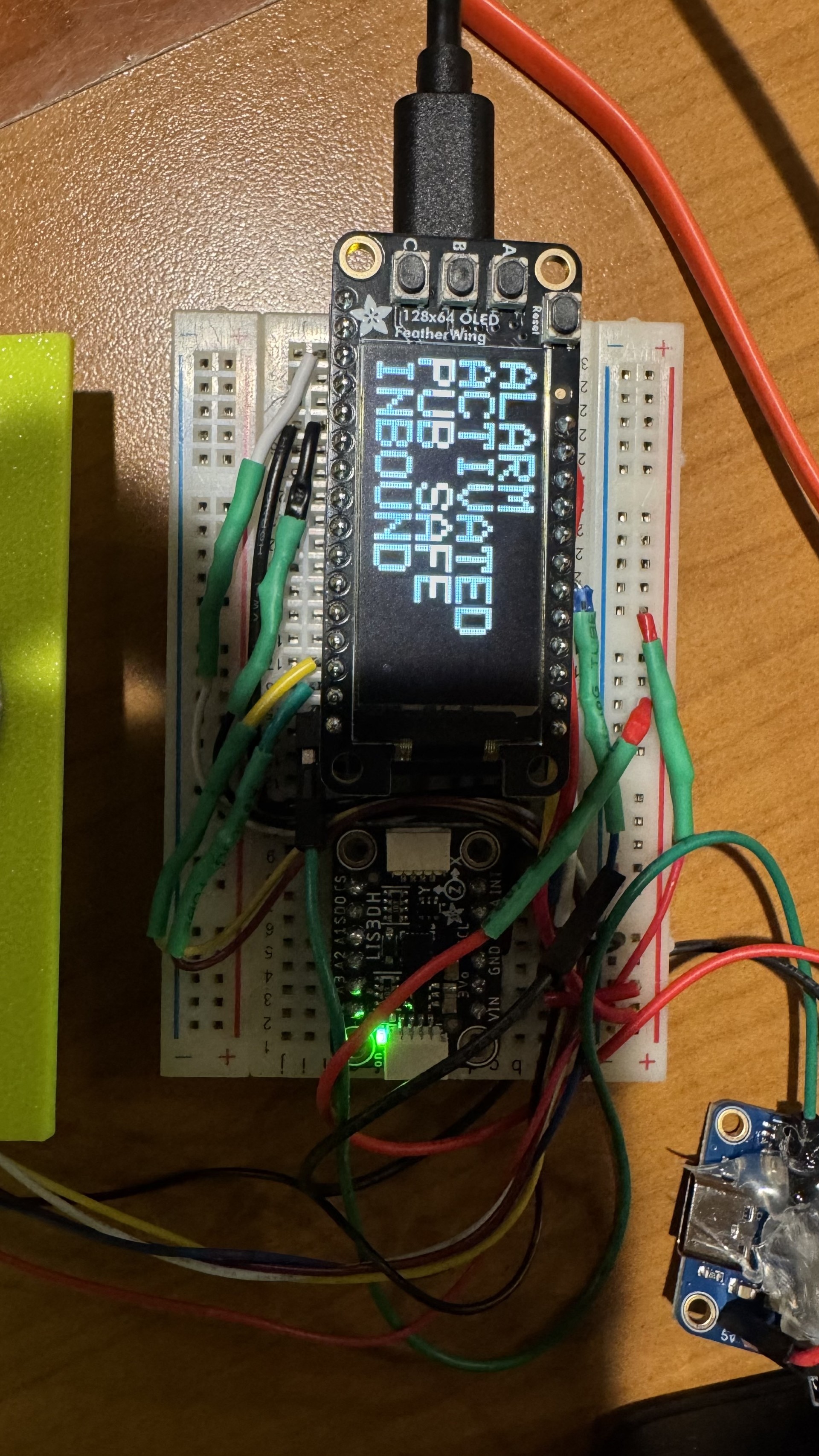
Here are the three main OLED screens, each activated with one of the three buttons when the device is awake

If the middle button is pressed while the system is disarmed, the screen walks the user through enrolling a new fingerpint
If the bottom button is pressed,the device shows the current GPS coordinates, and how much motion has occured since wake-up
The device also shows a threatening message when a theft event is detected
Accessibility
Although this product was designed with a bike in mind, there’s no reason this product couldn’t be used to secure any device that is intended to be secured. There are still some limitations in terms of accessibility, with the most prominent being the input device. The buttons are placed quite close together and labeled in very small text, so people with visual or motor disabilities may have trouble using it. Additionally, people with hearing disabilities would struggle to realize if they unintentionally set off the alarm, which may cause trouble for them or others in the area, given the volume of the horn.
Ethical Implications
The volume of the horn is the most identifiable impact that the device could have on a local population, Although unlikely, there is a possibility that the device gets triggered when someone unlocks their bike and jostles the user’s bike for an extended period of time. This would unnessecerily trigger a loud alarm. Whether unintentional or not, the horn going off may startle a thief and cause them harm if they crash the bike, and the local community may get aggrivated at the alarm sound.
Schedule
Our original schedule was as follows:
Finger Print Authentication (~1 week) We will begin by ensuring our FPA functions. This will consist of connecting the Fingerprint Sensor to our MCU and configuring it to verify certain finger profiles.
Accelerometer (~1 week) We will need to configure the SPI communication to be able to read data from the accelerometer and determine when motion is detected
Horn & Battery configuration & wiring (~1 week) Involves wiring the BTEDD through the MOSFET to the battery pack as well as using the Huzzah board to control power to the BTEDD
Wire the regulator from the Huzzah to the battery (~1 week) We will next connect our Car Horn to the MCU. Since the car requires 12 volts, it will be connected through a MOSFET directly to the 12v battery
GPS detection (~1 week) We will connect a GPS to the MCU, which will be usually sleeping. In the case of a BTE, it shall awaken, and will begin transmitting location data to the user through Adafruit IO. We are assuming the nature of the bike thief to be another student, so we will rely on campus Wi-Fi.
Adafruit IO Dashboard (~1 week) We will use the IO dashboard example code to push GPS and other data to a dashboard we can view
OLED Display (~1 week) We will use a small OLED display compatible with our MCU to indicate locking status as well as facilitate adding and deleting finger profiles. An LED will also be used as a more visible armed/disarmed indicator (Danny)
Due to the limitation of time we had to complete the project, the actual schedule went as follows:
Accelerometer (2 days)
GPS detection (2 days)
Adafruit IO Dashboard (2 days)
Finger Print Authentication (3 days)
OLED Display (1 day)
Horn & Battery configuration & wiring (~1 week)
Wire the regulator from the Huzzah to the battery (1 day)
We worked mostly asynchroniously on different tasks, but this was the general order in which tasks were completed. We had multiple problems with the horn and battery configuration, detailed below.
Issues
The first major issue we encountered was that the GPS module didn’t directly have a TX and RX line, which make up an SPI connection interface. The model GPS we bought was intended to connect to a computer or rasberry pi via a USB-C port, and formatted its pin outputs in terms of the USB-C transmission protocol. We realized we had purchased the wrong model GPS, but we figured out that we could directly solder wires to the physical GPS module, bypassing the conversion unit. Although the RX pin was soldered just fine, the delicate nature of the task resulted in the TX pin being ripped off of the module. This means that we can receive data from the GPS, which outputs constantly, but we can’t send input to it. Ultimately, this doesn’t affect the function of the product greatly.

When we integrated the code for the peripherals into the main code, it would output “invalid header” and get stuck in a boot loop. The same code functioned in Arduino IDE, so we had to do a lot of work to figure out why PlatformIO was struggling. The problem was with library versions, as in PlatformIO, we had the wrong library version. Arduino had the newest versions, so we had to manually update the libraries in PlatformIO.
Due to the large number of sensors that need to work at the same time, we encountered performance issues. We solved this by creating “task” modules, which are asynchronously ran, which doesn’t block the main code from running.
We are currently powering the system using TWO battery packs - the original 12v pack we ordered, and an extra 5v Anker portable charger we had. This is not our original plan, but we struggled to get the MCU successfully powered from pins, instead of the USB port. After researching, it is not recommended to power the board from the pinout at all.
A primary problem we encountered was getting out horn to work. Since the intensity of the of the horn is integral to the effectiveness of the project, we chose a 12 volt horn. This adds a complication to our whole system, as the rest of our units work at 5v. Since we were initially hoping to use only one power source, we got a 12v battery, a voltage regulator, and a MOSFET. Theoretically, we connect 12v power to the horn, and also run 12v into the regulator. We put the ground through the MOSFET, controlled by a 5v signal, either opening or closing the circuit. The most difficult part here being able to toggle the horn. In an initial test, it worked briefly, only blaring when we wished and then began to spark. Although not positive, we believed to have accidentally blown out the MOSFET. In later tests with a new MOSFET, we were able to make a circuit that controlled the horn with a small button. However, after disassembling this circuit to solder a more finalized version, we have not been able to get the horn to work again. We have verified that the horn still independently blares if connected directly to power, and we have measured the voltage and amperage being output to the horn. Unfortunately, we are reading 12v and 3a, so we are still unsure why the horn is not functioning.
Future work
We have two realms of future work: future polishing, to get our product to he desired presentable state, and more lofty future work, to turn our proof of concept into a more feasible product. To polish the product, the primary work includes figuring out the slight power supply issues, working through the horn (so it actually works), and integrating the Adafruit dashboard more completely. Currently, the user must access the GPS data through the AdafruitIO dashboard website. An app or text message system could be more convenient. Looking further ahead, the form factor of our finished product is not ideal for actual applications. It works as a proof of concept, but ideally the device would fit inside the hollow internal tubes of the bike frame. As it stands, a neon box will realistically be a target for thieves. It we were to integrate the product deeper into a bike, we could also develop a small lock, to physically restrain the bike as well as deter thieves.
References
-
Simmons, T. (2025, December 10). IUPD deploying “bait bikes” to fight back against campus bicycle thefts. WRTV Indianapolis. https://www.wrtv.com/news/local-news/in-your-community/monroe-county/iupd-deploying-bait-bikes-to-fight-back-against-campus-bicycle-thefts
-
Hangzhou Grow Technology. (2019). R503 Fingerprint Module User Manual. https://cdn-shop.adafruit.com/product-files/4651/4651_R503%20fingerprint%20module%20user%20manual.pdf
-
STMicroelectronics. (2011). AN3308 Application note. https://cdn-shop.adafruit.com/datasheets/LIS3DHappnote.pdf
-
Adafruit (2020) 128x64 OLED FeatherWing [Example code]. https://learn.adafruit.com/adafruit-128x64-oled-featherwing/arduino-code